The vertical cut in clay: 3.776, and what FEM gets
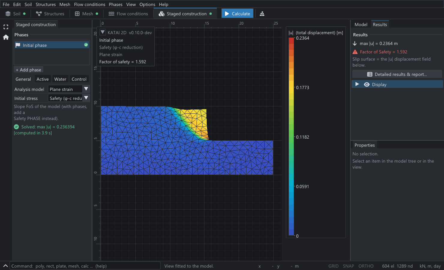
A vertical cut in undrained clay collapses when the stability number, unit weight times height over undrained strength, reaches a value that limit analysis has bracketed between 3.7752 and 3.7776. Computed by strength reduction in the open-source finite element program KATAI 2D, the number is 4.2000, 3.9810 and 3.8890 on three meshes of six-node triangles and 3.8287 on a mesh of fifteen-node triangles, 1.39% above the bracket. Every value approaches it from above, as a displacement method must. With the default tension cut-off the same cut gives about 2.2, because clay that cracks stands far less high.
How deep can you dig a vertical trench in clay before the side falls in? It is one of the oldest questions in soil mechanics and it has an unusually clean answer. For a soil with undrained shear strength and unit weight , the face of height collapses when the dimensionless group
reaches a critical value, the same for every clay and every height. There is no closed form for that value. But it is known to four significant figures, which makes it one of the sharpest tests a slope stability program can be given.
This article runs that test on KATAI 2D — software I write and maintain, so read it as a documented verification record rather than an independent review — with the published release 0.9.0 and a script of about fifty lines.
1. What is knownPermalink to “1. What is known”
The history of the number is a history of bounds closing in.
| Result | Kind | |
|---|---|---|
| Plane sliding wedge at 45° | 4 | upper bound |
| Circular slip surface through the toe | 3.83 | upper bound |
| Simple stress field (Drucker & Prager 1952) | 2.83 | lower bound |
| Numerical limit analysis, static approach (2010) | 3.7752 | lower bound |
| Numerical limit analysis, kinematic approach | 3.7776 | upper bound |
An upper bound comes from assuming a collapse mechanism: any mechanism that is kinematically possible fails at a load no smaller than the true one. A lower bound comes from finding a stress field that is in equilibrium and nowhere exceeds the strength: the true collapse load is no smaller than the load it carries. When the two meet, the answer is exact. Here they have met to within 0.064%, so
is as good as a closed form. For the cut used below — 5 m high, in clay with kPa and kN/m³ — the factor of safety is 1.5104, and the same clay would stand vertically to 7.55 m.
Those bounds are for a Tresca material: one whose strength is the same in tension as in compression. That qualification turns out to matter, and section 5 is about it.
2. The modelPermalink to “2. The model”
import katai

H, GAMMA, CU = 5.0, 20.0, 40.0

def cut(element, mesh_size, tension_cutoff):
    prj = katai.Project("Vertical cut in undrained clay", element=element,
                        mesh_size=mesh_size, auto_refine=False)
    clay = prj.materials.mohr_coulomb("Clay", E=1.0e5, nu=0.3, c=CU, phi=0.0,
                                      gamma=GAMMA, tension_cutoff=tension_cutoff)
    # L-shaped section, counter-clockwise from the bottom-left corner: retained
    # ground 3H wide and 2H deep, the cut face at x = 3H, the floor 2H wide.
    prj.geometry.polygon(
        [(0, 0), (5 * H, 0), (5 * H, H), (3 * H, H), (3 * H, 2 * H), (0, 2 * H)],
        material=clay,
        fix=["full", "horizontal", "free", "free", "free", "horizontal"])
    prj.initial(procedure="safety")
    return prj

fos = cut("tri15", 1.0, tension_cutoff=False).run().results()[-1].fos
print(fos * GAMMA * H / CU)        # the stability number
One L-shaped polygon. The ground continues a full cut height below the floor and three cut heights behind the face, so that the mechanism is not steered by a boundary. The clay is Mohr–Coulomb with , which is Tresca, and the factor of safety comes from strength reduction: the stability number is that factor times .
tension_cutoff=False is what makes the model the one the bounds describe. By default
KATAI 2D, like most geotechnical programs, limits tensile stress to zero.
3. ResultsPermalink to “3. Results”
| Element | Target size | Nodes | Factor of safety | Above 3.776 | |
|---|---|---|---|---|---|
| 6-node | 2.0 m | 356 | 1.6800 | 4.2000 | +11.23% |
| 6-node | 1.0 m | 1289 | 1.5924 | 3.9810 | +5.43% |
| 6-node | 0.5 m | 5016 | 1.5556 | 3.8890 | +2.99% |
| 15-node | 2.0 m | 1331 | 1.5594 | 3.8985 | +3.24% |
| 15-node | 1.0 m | 4993 | 1.5315 | 3.8287 | +1.39% |
Three things are in that table.
Every value is above the bracket. A displacement finite element model restricts the soil to the deformations its elements can represent. That is a kinematic restriction, so the model is stiffer and stronger than the continuum and its collapse load is an overestimate — for the same reason an assumed slip circle gives an upper bound. A finite element result below 3.7752 would not be a better answer; it would be a bug.
Refinement closes the gap, monotonically. Halving the element size takes the six-node result from 11.23% to 5.43% to 2.99% above the reference.
The element matters more than the mesh. The fifteen-node triangle on the 2 m mesh (1331 nodes) is as close as the six-node triangle on the 0.5 m mesh (5016 nodes), and on its own 1 m mesh it is within 1.39%. Collapse in undrained clay is incompressible flow, and a quartic displacement field accommodates the incompressibility constraint far more easily than a quadratic one. This is the reason geotechnical programs offer the higher-order element for limit loads, shown here on a problem where the right answer is known.
3.1 Extrapolating the six-node seriesPermalink to “3.1 Extrapolating the six-node series”
Three meshes with a refinement ratio of 2 allow a Richardson extrapolation. The successive differences are and , a ratio of 2.380, so the observed order of convergence is
and the extrapolated value is
which is 1.23% above the reference. Two cautions belong with that number. The meshes are unstructured and generated independently at each size, not nested, so the series is only approximately a systematic refinement. And an order of 1.25, well below the element’s formal order, is what a singular problem looks like: the stress field has a singularity at the toe of the cut, and the mechanism is a thin shear band whose resolution improves only linearly with element size. The extrapolation narrows the gap; it does not close it.
4. Reading the result as an engineerPermalink to “4. Reading the result as an engineer”
For the cut analysed here the exact factor of safety is 1.5104. The meshes above give between 1.5315 and 1.6800. On the coarsest mesh the model says the cut has 11% more margin than it has; on a reasonable one, 1.4%.
The direction of that error is the important part. A displacement finite element collapse load errs on the unsafe side, always, and by an amount that depends on the mesh near the failure surface. A factor of safety of 1.31 from a coarse model of a slope that needs 1.3 has not demonstrated 1.3. The remedy is not exotic — refine near the mechanism, use the higher-order element, and look at how much the answer moves — but it has to be done, and it can only be calibrated on problems like this one where the true answer is on record.
5. Clay that cracksPermalink to “5. Clay that cracks”
Everything so far assumed the clay can carry tension. Real clay near a free vertical face often cannot: it cracks.
Run the same model with the tension cut-off left at its default of zero and the result changes completely:
| Element | Target size | , tension carried | , tension cut off |
|---|---|---|---|
| 6-node | 2.0 m | 4.2000 | 2.2687 |
| 6-node | 1.0 m | 3.9810 | 2.3433 |
| 15-node | 2.0 m | 3.8985 | 2.1688 |
The stability number falls by 41 to 46%. That is not a numerical accident. Drucker (1953) showed that for a soil unable to take tension the upper bound on the critical height of a vertical cut drops to half of the plane-wedge value, that is to ; and the elementary lower bound — vertical stress , no horizontal stress, which needs no tension anywhere — is also 2. For a no-tension clay, then, the stability number is 2, against 3.776 for one that carries tension.
The finite element values with the cut-off on are 2.17 to 2.34: between 8% and 17% above that 2, and — unlike the tension-carrying series — not falling steadily with refinement. I report them as they are. The collapse of a cracking face involves soil separating and toppling, which a continuous displacement field represents poorly, and these three numbers should be read as showing the size and direction of the effect, not as a converged value.
The practical point survives the imprecision. The 5 m cut with a factor of safety of 1.51 has, if its clay cracks, a factor of about 0.87 to 0.94 in these models — and by Drucker’s bound exactly 0.80. It does not stand. Whether a finite element analysis of an unsupported cut includes a tension cut-off is not a detail of the settings dialog; it is most of the answer, and the default in this program is the conservative one.
6. What this does and does not establishPermalink to “6. What this does and does not establish”
- It establishes that the strength reduction in KATAI 2D approaches the bracketed stability number of a Tresca vertical cut from above, monotonically under refinement, reaching +1.39% with fifteen-node elements at a 1 m mesh on a 5 m cut.
- It quantifies the discretisation error of a collapse load on a problem with a singular corner: 3 to 11% for six-node elements at the sizes tried.
- It does not establish convergence for the no-tension case, where three values between 2.17 and 2.34 are reported against a theoretical 2 and no trend is claimed.
- Undrained, total stress, homogeneous. A real excavation has a strength profile, a water table, a time scale over which the undrained assumption expires, and usually a surcharge at the crest. None of them is in this benchmark.
7. Reproducing thisPermalink to “7. Reproducing this”
| What | Where |
|---|---|
| Script | vertical_cut_undrained_clay.py |
| Project files | 6-node 2 m · 6-node 1 m · 6-node 0.5 m · 15-node 2 m · 15-node 1 m · 15-node 2 m, cracking |
| Program | KATAI 2D 0.9.0, the published wheel, in a clean virtual environment |
| Run time | 10 s to 9 min per case on a 2017 laptop, growing with the mesh |
The project files run from the command line with katai solve and open in the desktop
application. Every figure quoted on this page is recomputed from its stated inputs by a
script that runs on each build of this site.
ReferencesPermalink to “References”
- Drucker, D. C. & Prager, W. (1952). Soil mechanics and plastic analysis or limit design. Quarterly of Applied Mathematics 10(2), 157–165. — the bound theorems and the first bounds on the vertical cut.
- Drucker, D. C. (1953). Limit analysis of two- and three-dimensional soil mechanics problems. Journal of the Mechanics and Physics of Solids 1(4), 217–226. — the cut in a soil unable to take tension.
- Taylor, D. W. (1937). Stability of earth slopes. Journal of the Boston Society of Civil Engineers 24, 197–246. — the circular-arc value 3.83.
- Kammoun, Z., Pastor, F., Smaoui, H. & Pastor, J. (2010). Large static problem in numerical limit analysis: a decomposition approach. International Journal for Numerical and Analytical Methods in Geomechanics 34(18), 1960–1980. — the lower bound 3.7752, and the upper bound 3.7776 it is compared with.
- Roache, P. J. (1994). Perspective: a method for uniform reporting of grid refinement studies. Journal of Fluids Engineering 116(3), 405–413. — Richardson extrapolation and the observed order.
- KATAI 2D 0.9.0. github.com/fkkarakurt/katai2d, Apache-2.0. doi.org/10.5281/zenodo.20692282.